PRODUCT CENTER / COMPLETE SYSTEMS
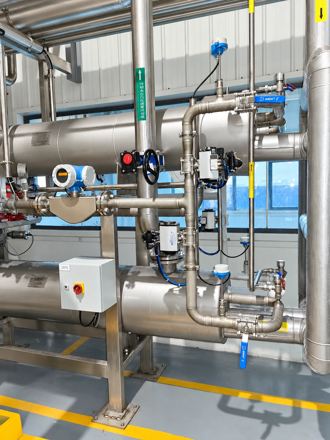
CO₂ Liquefaction Plant
Liquefaction converts conditioned CO₂ into liquid for storage, transport or further processing. The plant must coordinate inlet purity, drying, non-condensable management, refrigeration and storage pressure.
| Project element | Design basis |
|---|---|
| Feed | Conditioned CO₂ within an agreed composition and moisture envelope |
| Product | Liquid CO₂ at specified transfer conditions |
| Critical interfaces | Pretreatment, refrigeration, storage and vent systems |
APPLICATION OVERVIEW
Make liquid production fit the available gas.
01
Inlet envelope
Specify composition, moisture, pressure, temperature and flow range. A liquefier quote should state precisely which upstream treatment is included.
02
Refrigeration duty
Determine refrigeration and cooling duties at the site’s climatic conditions. When comparing quotations, check which equipment and liquid CO₂ output are included in the kWh/t figure.
03
Light-gas management
Understand the effect of oxygen, nitrogen and other non-condensables on product quality, venting and recovery. A purity target and recovery target must be evaluated together.
04
Storage integration
Define transfer conditions, storage operating range, inventory control and loading interfaces. Uncoordinated boundaries can lead to unnecessary venting or operating restrictions.
FROM SOURCE TO PRODUCT
CO₂ liquefaction process and refrigeration equipment
The route below illustrates a CO₂-rich feed. Flue gas needs upstream capture; biogas-derived streams need upstream separation and source-specific conditioning.
Match the plant to the gas source.
A gas holder or collection system balances variable production. Source acceptance and controlled diversion protect the downstream process from unsuitable gas.
Prepare the gas for compression.
Pretreatment depends on source contaminants. Fermentation carryover, soluble impurities, sulfur species and solvent traces require different treatment and monitoring strategies.
Create the required process conditions.
Compression and intercooling support the selected purification and liquefaction route. Liquid separation and machine protection are engineered around actual inlet conditions.
Control more than CO₂ percentage.
Adsorption and other selected purification stages manage water and specified trace contaminants. Bed regeneration and switching must preserve product quality throughout the operating cycle.
Produce liquid CO₂ to the agreed specification.
Refrigeration condenses CO₂. Refining and vent management address light gases where required. Product testing determines acceptance; liquefaction alone does not establish food-grade status.
Protect quality to the point of use.
Liquid storage, loading or vaporization must preserve product quality and comply with applicable pressure-system requirements. Operating procedures and traceable quality records complete the system.
PROCESS EQUIPMENT
CO₂ washing & pretreatment
Washing and pretreatment address selected contaminants and entrainment before downstream processing.
Explore equipmentPROCESS EQUIPMENT
CO₂ compression systems
Compression establishes pressure for the selected purification and liquefaction route.
Explore equipmentPROCESS EQUIPMENT
CO₂ adsorption & drying
Drying controls water before cold processing and product delivery.
Explore equipmentSPECIFICATION & SCOPE
CO₂ liquefaction plant capacity and utilities
We develop the process around the gas analysis, flow profile and required product. State every critical impurity limit and the measurement method alongside the CO₂ concentration.
| Item | Project definition |
|---|---|
| Feed | Conditioned CO₂ within an agreed composition and moisture envelope |
| Product | Liquid CO₂ at specified transfer conditions |
| Critical interfaces | Pretreatment, refrigeration, storage and vent systems |
| Performance comparison | State operating point, utility boundary and measurement method |
| Acceptance | Capacity, consumption and product quality verified to the agreed test plan |
Capacity, utility consumption and product guarantees are finalized in the project proposal at agreed inlet conditions. Compare the scope, utility boundaries and acceptance tests using our CO₂ plant procurement and acceptance guide.
RELEVANT YTC EXPERIENCE
Related CO₂ recovery project references
Compare source, scale and specification with your own requirements.
FREQUENTLY ASKED QUESTIONS
CO₂ liquefaction plant questions
Does liquefaction remove every impurity?
No. Different contaminants behave differently. Upstream conditioning and specific purification stages may be required.
Can liquefaction be added to an existing recovery system?
Potentially. The inlet gas quality, pressure, flow range, utilities and storage interfaces must first be checked.
For food and beverage applications, review source qualification and the selected sample reports.
TECHNICAL INSIGHT
Understand the design decisions.
Define the inlet before selecting the cold system
A liquefaction plant is specified around a gas inlet envelope and a liquid-product delivery point. Flow, composition, moisture, pressure and temperature determine the treatment and refrigeration work between them. If one proposal starts with dry compressed CO₂ and another starts with wet low-pressure gas, their equipment prices and energy figures do not describe the same service.
The inlet envelope should include the minimum and maximum flow and the non-condensable content. Oxygen, nitrogen and other lighter gases can accumulate at the cold end and affect venting and product quality. Their treatment has to be coordinated with the required recovery fraction; removing contaminants while retaining CO₂ is a separation problem, not a free by-product of cooling.
Compare capacity at realistic site conditions
Refrigeration performance depends on the temperature at which heat is rejected as well as the cold duty. Site climate, cooling-water conditions, altitude where relevant and equipment cleanliness assumptions should appear in the design basis. A nominal capacity quoted at favorable conditions may not represent output during the hottest production period.
Part-load operation also matters. A plant designed for a relatively steady merchant-gas source has a different operating pattern from one following batch fermentation. Ask how the selected arrangement handles turndown, restart and changing feed without claiming that a single efficiency figure applies across the entire range.
Connect liquid production to storage and dispatch
The liquid transfer boundary establishes conditions at the storage inlet and the responsibilities for piping, valves, pressure management and inventory control. Storage can buffer dispatch variation, but it does not eliminate the need to match average output to average offtake. Loading and downstream vaporization may introduce additional quality or utility requirements.
Our proposal can be compared most clearly when the acceptance basis identifies inlet conditions, delivered liquid mass, product specification and the complete utility boundary. Metered energy should cover the equipment actually included in that boundary. Keeping these details explicit makes capacity and consumption discussions meaningful for both a new plant and an expansion of an existing system.
Questions for the technical review
Why must energy figures state the inlet pressure?
The work needed to reach liquefaction conditions changes with the incoming gas state. Excluding upstream compression can make two energy figures incomparable.
Does a bigger storage tank increase liquefier capacity?
It can improve scheduling flexibility, but it does not increase the process equipment’s sustained production rate.
START WITH YOUR SOURCE
Turn your CO₂ source into a defined project.
Send your gas analysis, flow profile, product target and project location. We will help connect the technical questions with a practical supply scope.
CONTINUE YOUR TECHNICAL REVIEW
Connect the specification with the evidence.
Relevant references
Review source, nominal capacity and the recorded supply scope.
Explore ↗ENGINEERING TOOLAssess your CO₂ source
Estimate recoverable quantity using visible assumptions.
Explore ↗BUYING GUIDEPrepare your specification
Define feed conditions, quality, utilities and acceptance before comparing proposals.
Explore ↗